Electromagnetic induction
A conductor moving across a magnetic field or a changing magnetic field linking with a conductor can induce an e.m.f. in the conductor.
- Electromagnetic induction – Magnetic fields can be used to produce an electric current.
- Galvanometer — Used to show the intensity and direction of a current
Practical: Moving wire
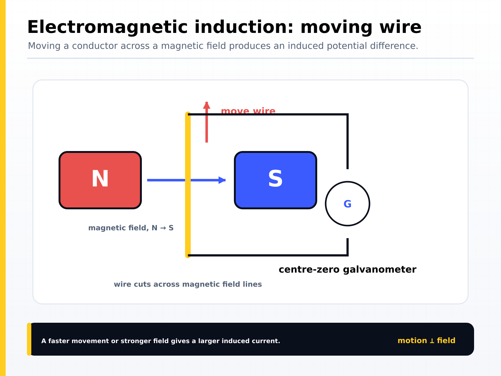
Observations
- When the wire is moved downwards, the galvanometer deflects to one side briefly and returns to the centre.
- When the wire is moved upwards, the galvanometer deflects to the opposite side briefly.
- If the wire is moved sideways there is no deflection on the galvanometer.
- If the wire is kept stationery in between the poles of the magnet, there is no deflection.
- If the wire is moved up or down faster, a greater deflection is observed.
Conclusions
- A current is only induced in the wire when the wire cuts across the magnetic field lines of the magnet.
- If the wire moves parallel to the field lines (if it doesn't cut them), no current is induced.
- If the wire is not moving there is no current that is induced in the wire.
- Increasing the speed of the wire increases the amount of current that is induced.
Practical: Bar magnet & coil
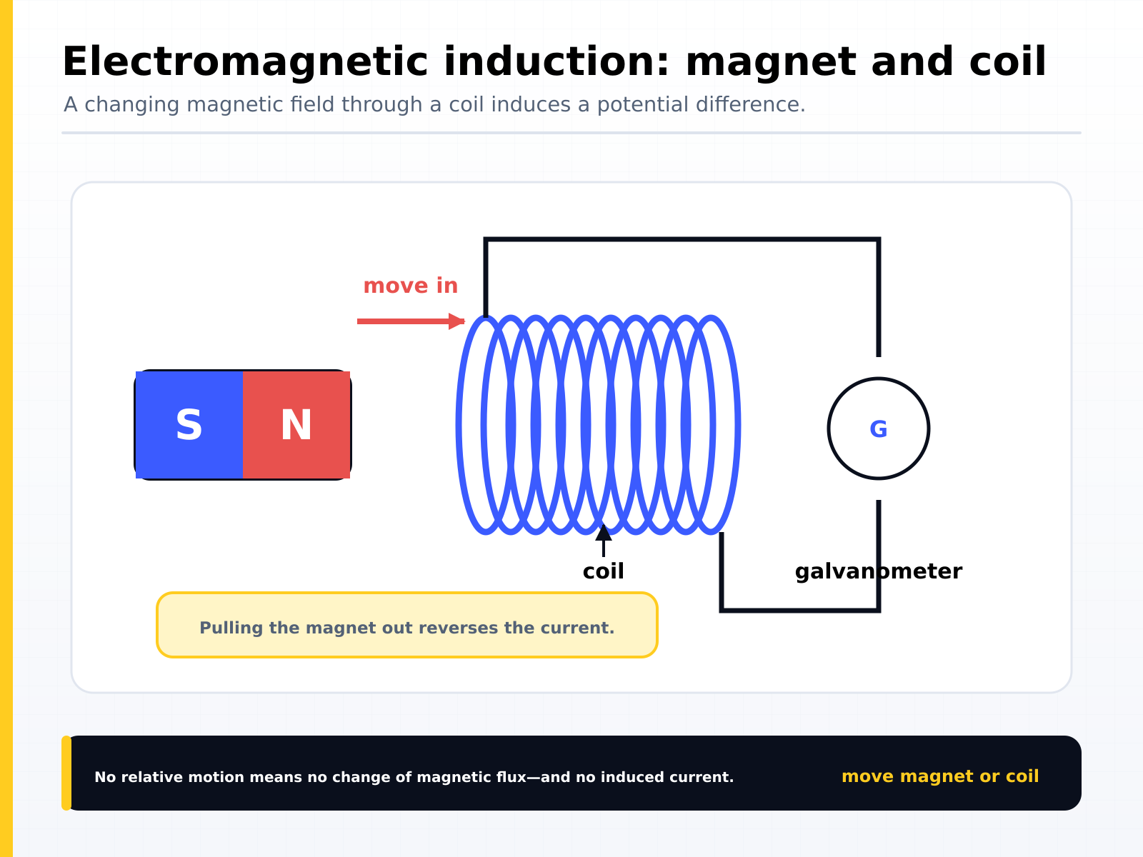
Observations
- When the magnet is pushed into the coil, the galvanometer deflects to one side briefly and returns to the centre.
- When the magnet is pulled out of the coil, the galvanometer deflects to the opposite side.
- If the magnet is held stationary inside the coil, there is no deflection on the galvanometer.
- If the magnet is moved in or out faster, a greater deflection is observed.
Conclusions
- A current is only induced in the coil when the field lines of the magnet cut across the wires of the coil.
- If the magnet is not moving there is no current induced in the wire.
- Increasing the speed of the magnet increases the amount of induced current.
Increase induced current:
- Move magnet faster
- Adding more turns to coil
- Increasing strength of magnet.
The a.c. generator
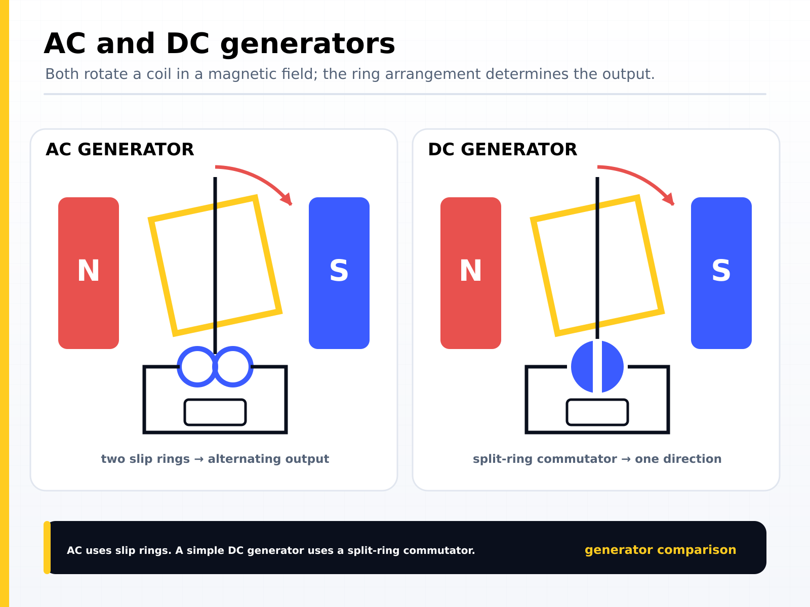
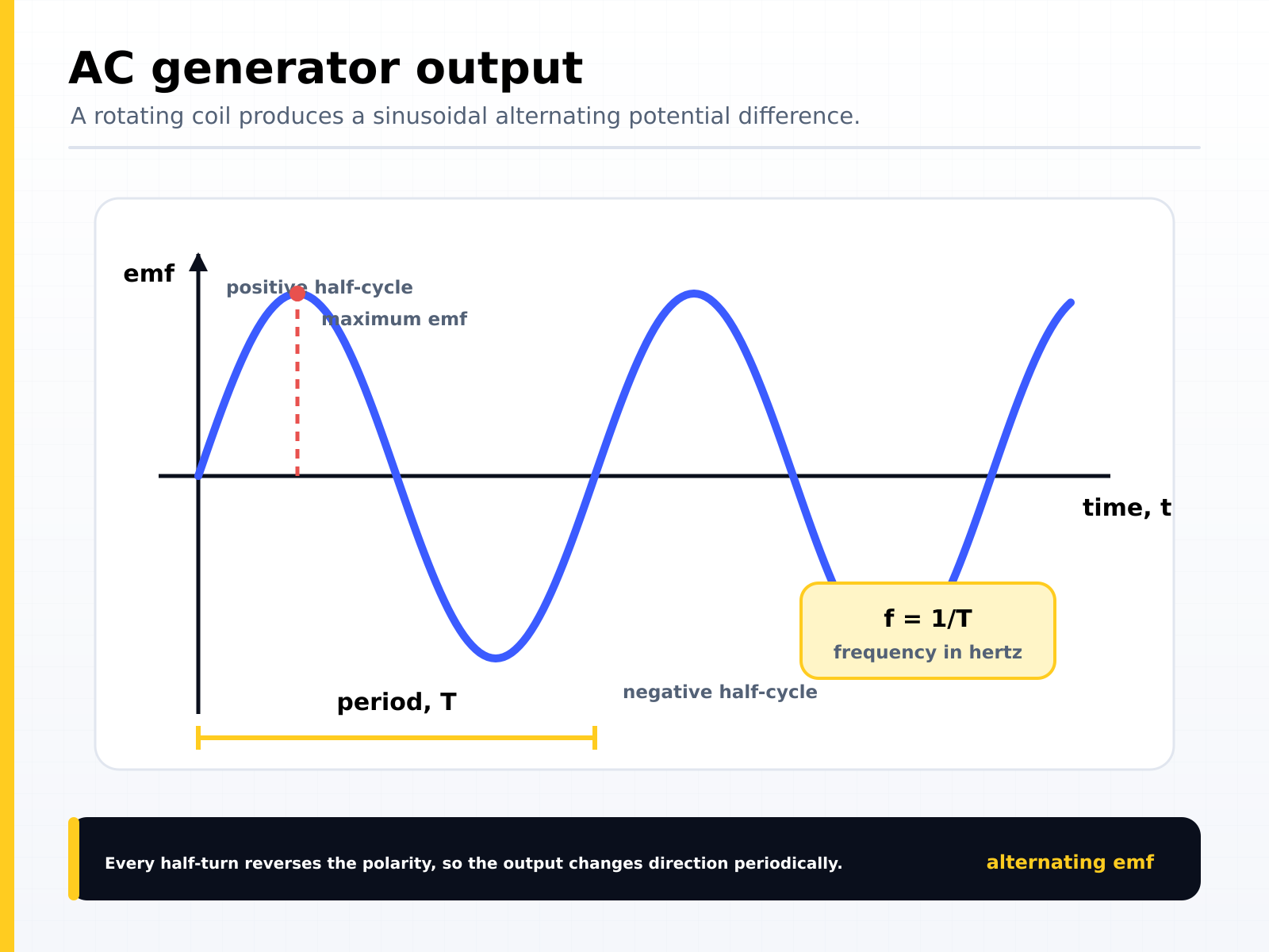
A.c. generator consists of a coil of wire rotating in a magnetic field. It is used in power stations in the large-scale generation of electricity to supply homes and factories.
Consists of:
- Slip rings – transfers power between the rotating and stationary structure of an AC machine.
- Brushes – makes continuous contact between the external circuit and slip rings.
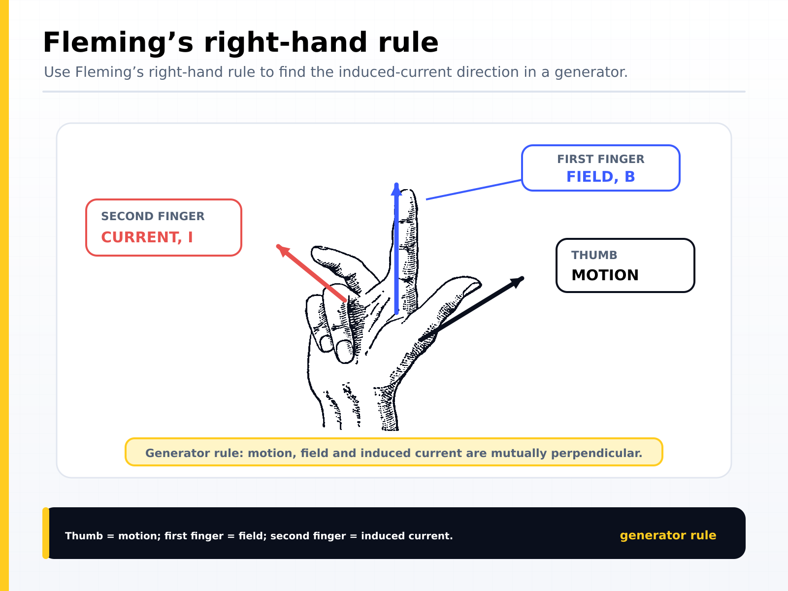
To find direction of current, force and magnetic field, use Flemmings right hand rule.
Magnetic effect of a current
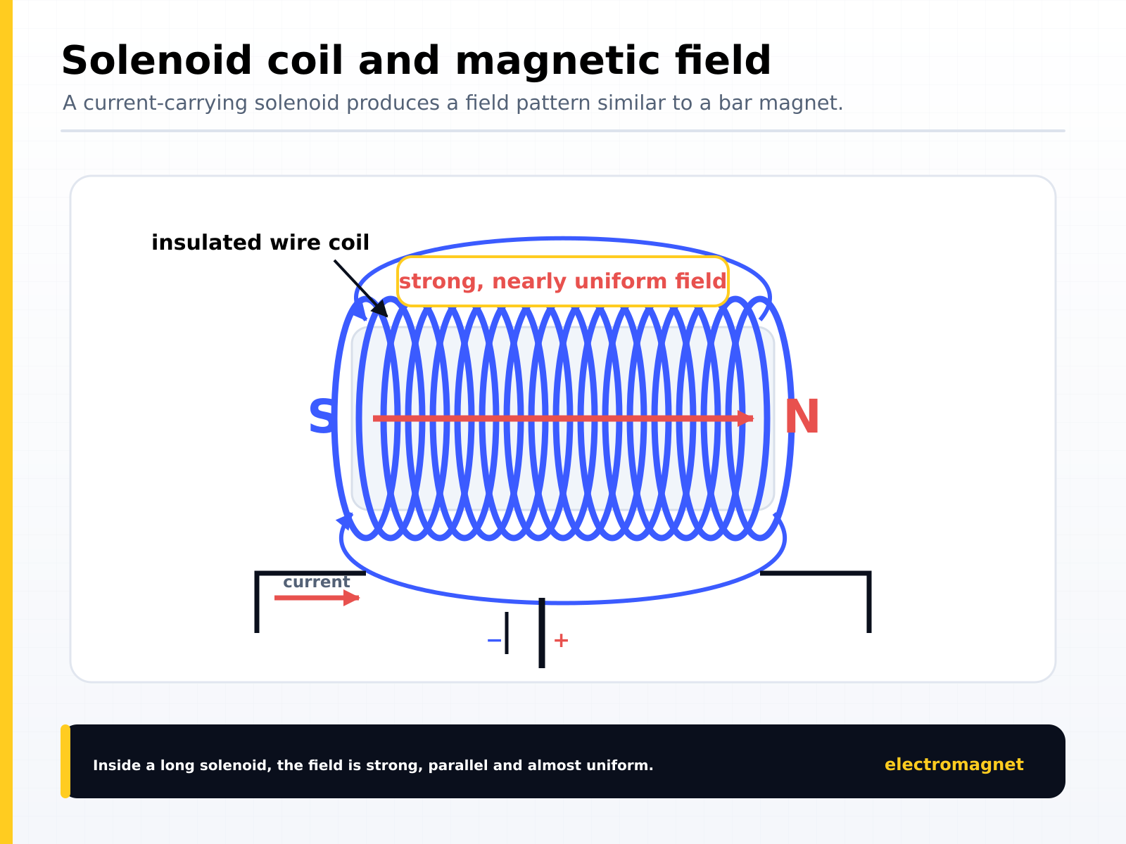
Solenoid (a coil of wire)
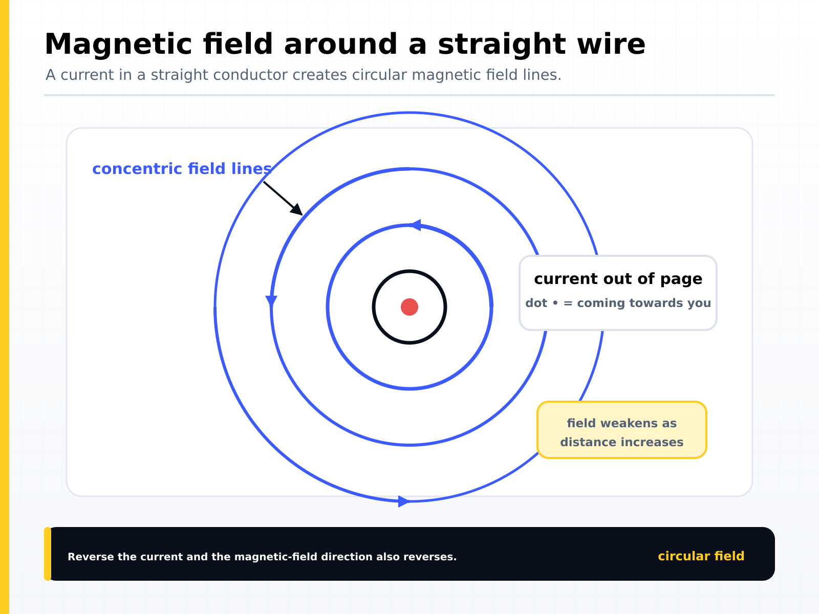
- Straight wire
- The field lines are close together at the poles of the electromagnet
- Further from the coil, the weaker the field.
- Inside the coil, the field lines run parallel to each other showing that the field is uniform.
- Increasing the current gives a stronger field.
- The polarity of the field is reduced when the current is reversed.
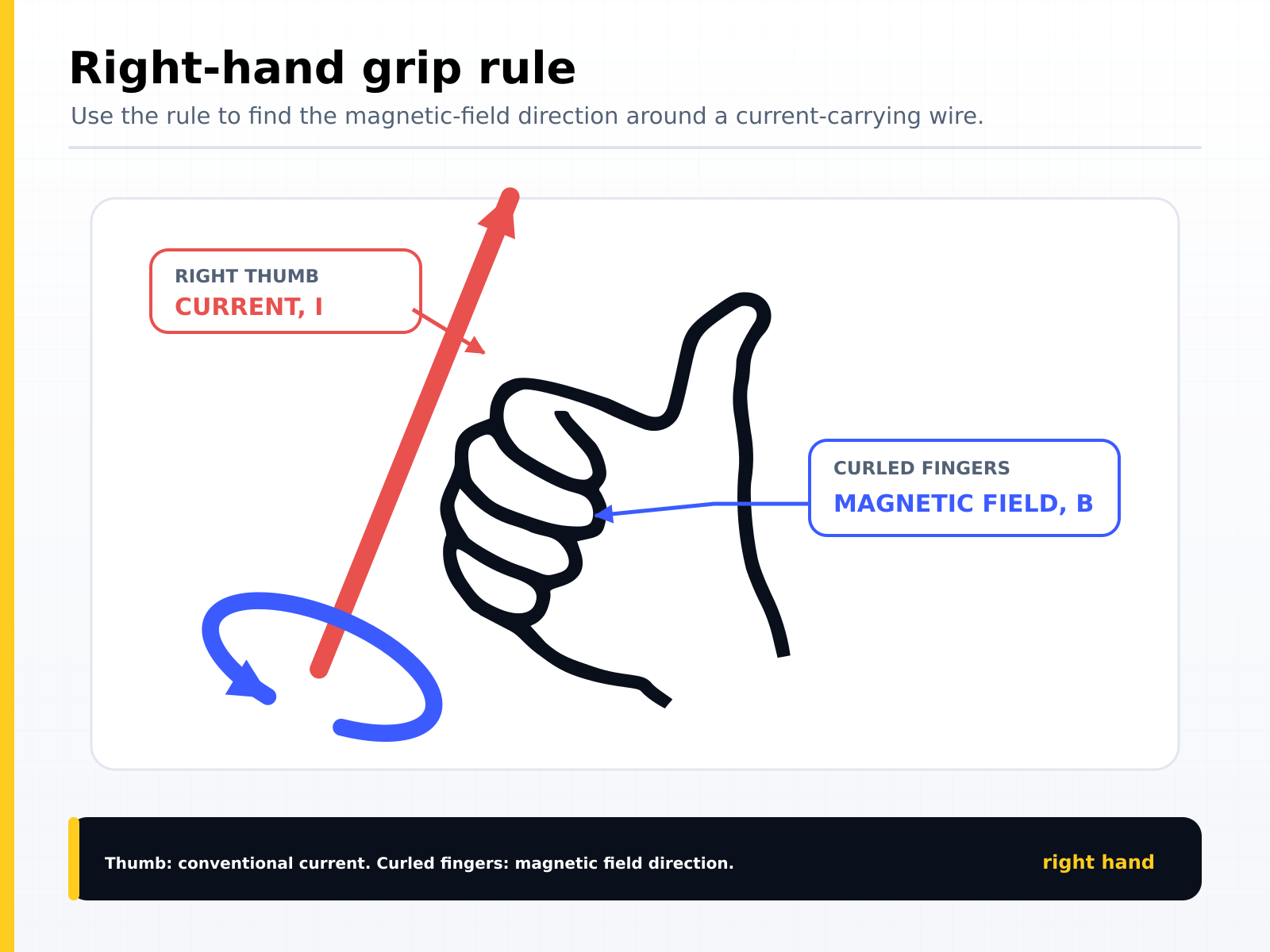
- The field lines are circles around the wire.
- Further away from the wire, the weaker is the field.
- If the current is greater, the field will be stronger (lines will be closer together)
- Reversing the current, reverses the direction of the field.
Relay
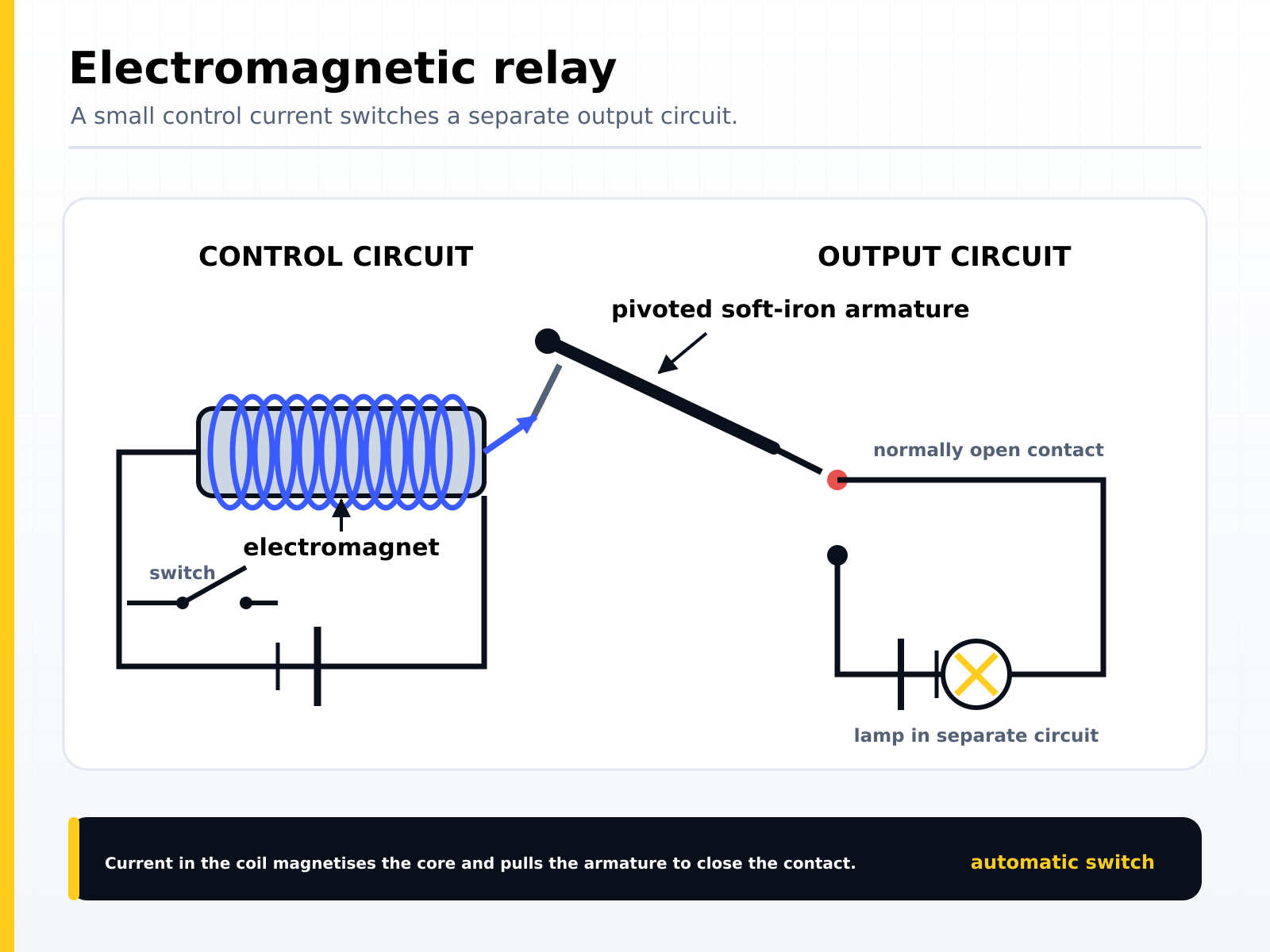
- A relay uses an electromagnet and consists of 2 circuits.
- Input circuit is a simple electromagnet, which requires a small current.
- When the switch is closed, current flows and the coil becomes an electromagnet.
- The coil attracts the steel switch in output circuit, closing the switch.
- Large current flows in the output circuit to operate powerful motor.
Examples of relay: Ignition key to start a car, TV remote.
Force on a current-carrying conductor
If the current-carrying wire is placed in a magnetic field (whose lines of force are at right angles to wire) then it will experience a force at right angles to both the current direction & magnetic field line.
Charged Particle in Magnetic Field
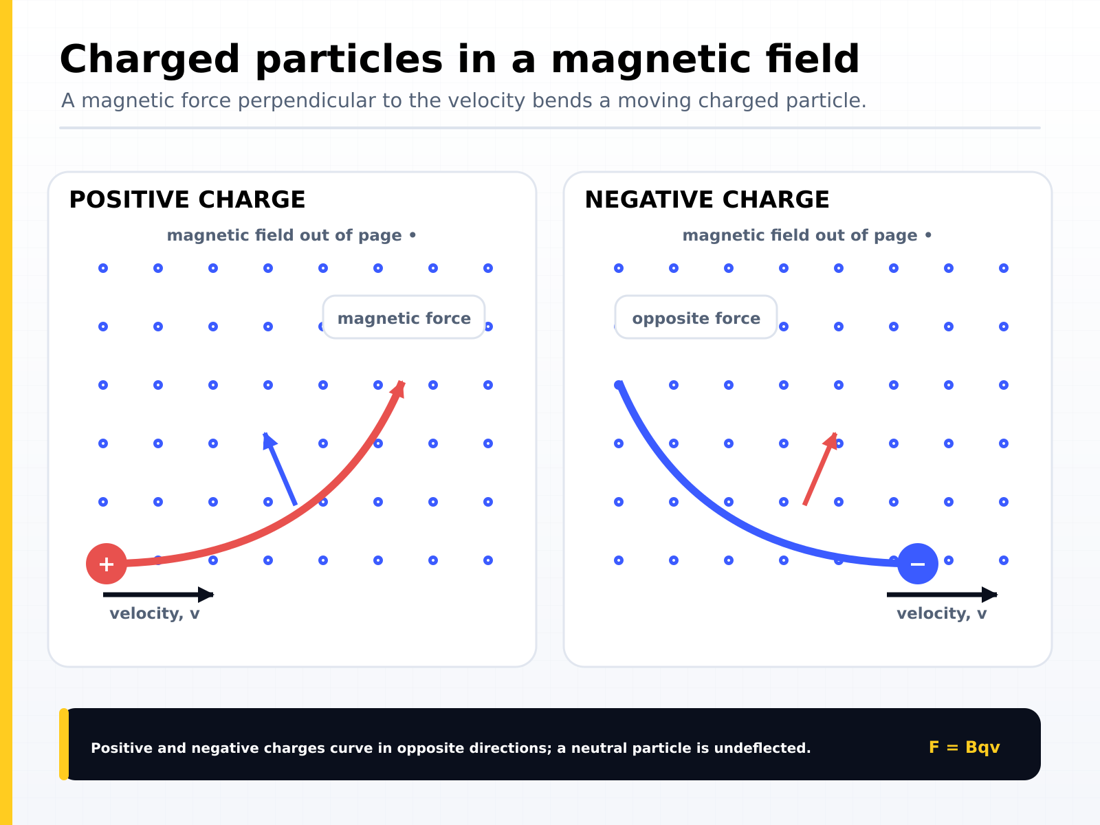
- A charged particle experiences a force when moving through a magnetic field.
- If the field is in a vacuum, the magnetic field determines the motion.
- Since the magnetic force is perpendicular to the direction of travel, a charged particle follows a curved path in a magnetic field.
The d.c. motor
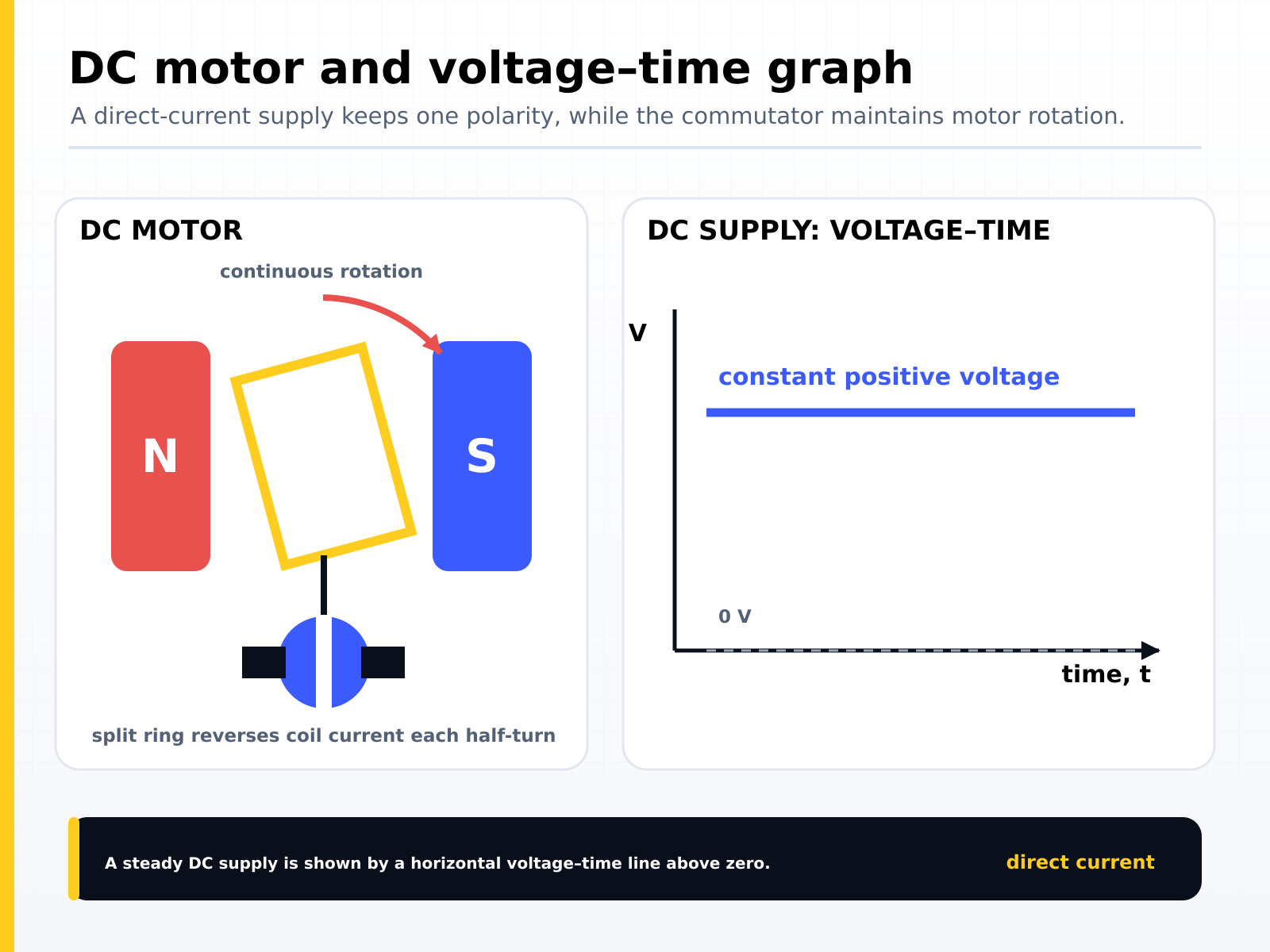
A current-carrying coil in a magnetic field may experience a turning effect. The turning effect can increase by:
- Increasing number of turns on the coil
- Increasing the current
- Increasing the strength of the magnetic field
Electric motor – device transforming electrical energy into mechanical (kinetic) energy.
- A simple electric motor is built so that a coil of wire connected to an electric circuit is free to rotate between two opposite magnetic poles.
- When electric current flows, one side of the coil experiences downward force, and the other side of the coil experiences upward force.
- The wire starts to rotate counterclockwise.
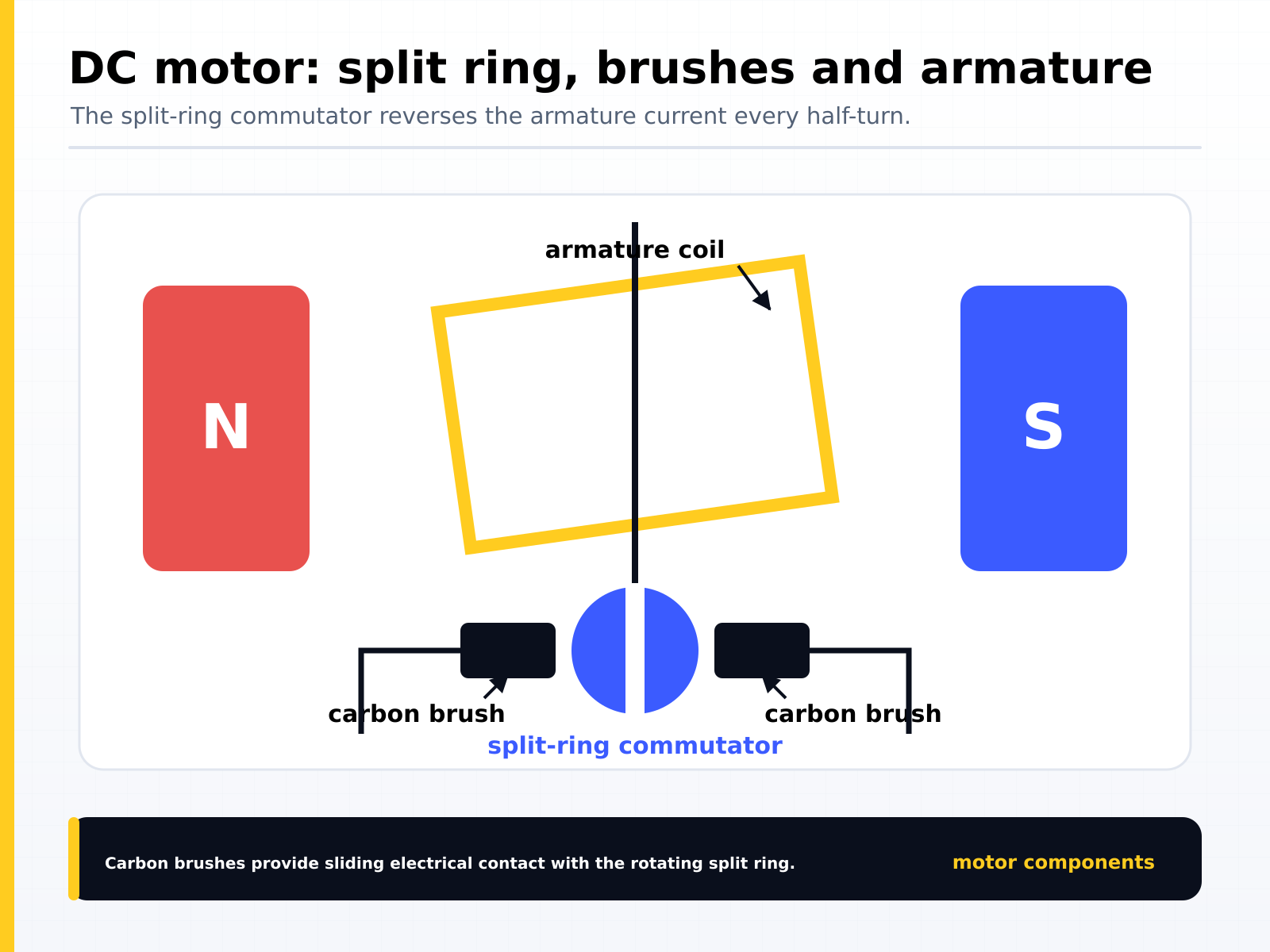
- To make the rotation continuous, the commutator changes the direction of current flow every half rotation.
Split ring commutator - swaps the contacts of the coil
- This reverses the direction in which the current is flowing every half turn.
- This will keep the coil rotating continuously as long as the current is flowing.
Brushes – makes continuous contact between the external circuit and slip rings.
To find direction of current, force and magnetic field, use Flemmings left hand rule.
The transformer
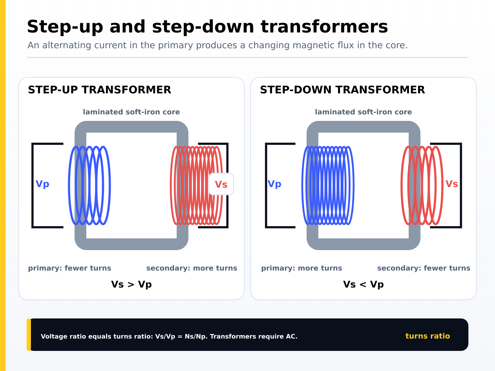
A simple transformer is used for voltage transformations.
Structure of transformers:
- Iron core, 2 coils of wire:
- Primary coil from the a.c. input
- Secondary coil leading to the a.c. output.
| Step-up transformer | Step-down transformer |
|---|---|
| Increases the p.d. for power line transmission | Decreases the p.d. (voltage) of the power line transmission. |
Where V = voltage and N = number of turns on the coil
How transformers work:
- Alternating current will create change in magnetic field.
- Iron core will transfer magnetic field to secondary coil.
- Magnetic field cuts the secondary coil.
- E.m.f. of current will be induced.
Transformers are used in high-voltage transmission of electricity.
Why High Voltage:
- Increase efficiency. As electricity is transmitted over long distances, energy is lost along the way.
- High voltage transmission minimises power loss.
- The higher the voltage, the lower the current. The lower the current, the lower the resistance losses in the conductors. And when resistance losses are low, energy losses are low also.